
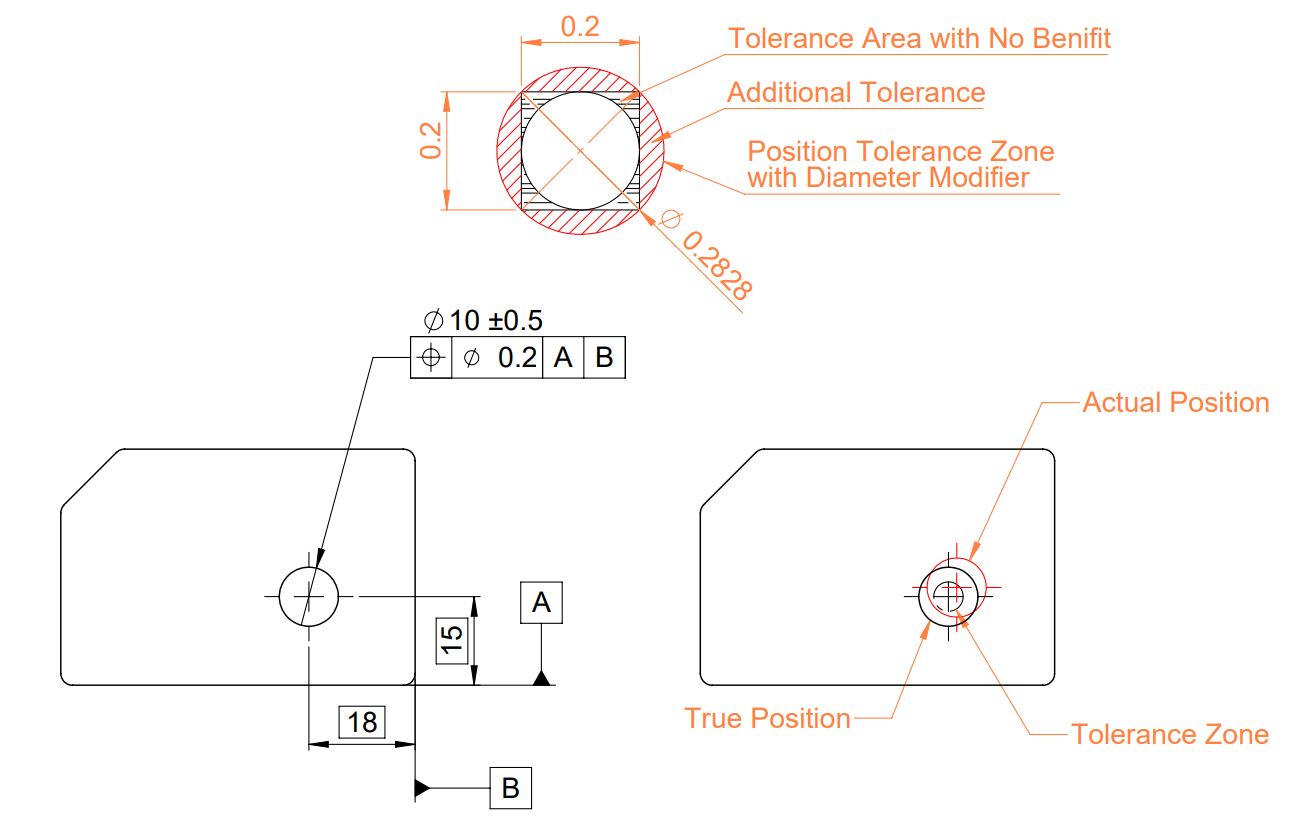
Use the following formula to calculate radial hypotenuse value multiply by 2 for the diametrical position tolerance. The position tolerance is the gd&t symbol and tolerance of location.

Gdt Interpretation Training Geometric Dimensioning And Tolerancing Gdt Basics Training Y145 Standard Gdt Software Train Geometric Solidworks
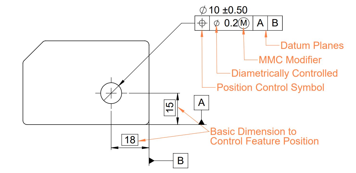
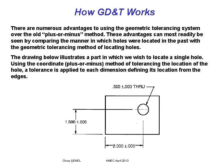
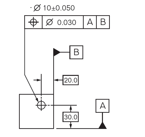
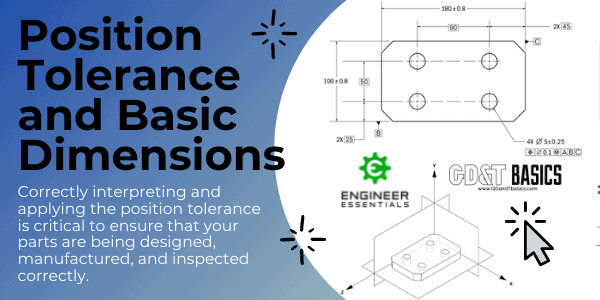
When using the position gd&t callout to locate holes, the position is established from datum references in the feature control frame.
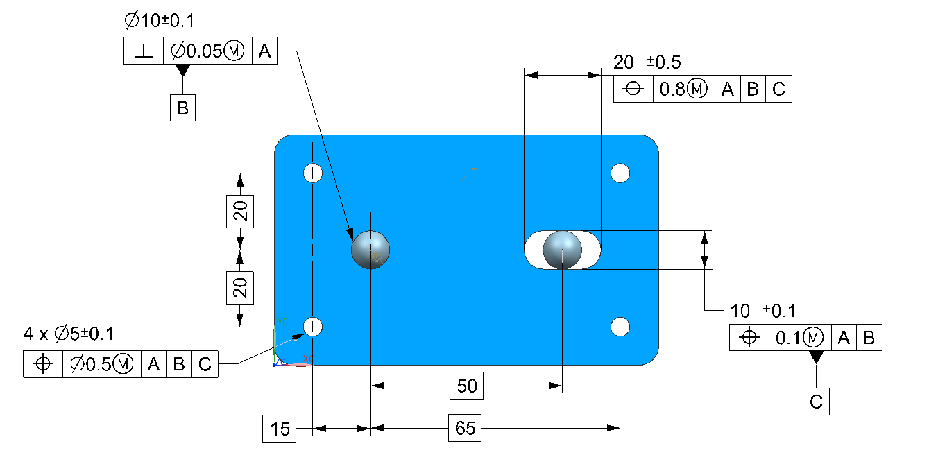
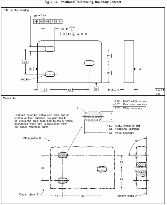
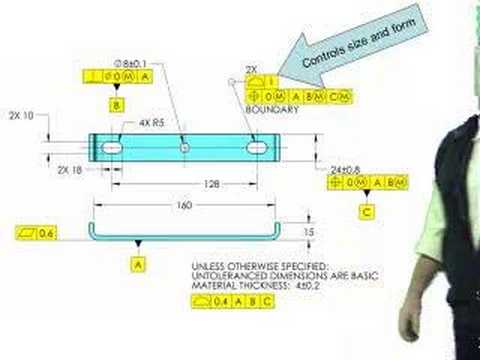
Gd&t slot position tolerance. It eliminates ambiguities hence everyone that is Therefore actual gd&t position tolerance measured against 0.25 is 0.30. This has a feature size tolerance of ±0.5 mm and a position tolerance of 0.8 mm at mmc with respect to datum reference frame abc.
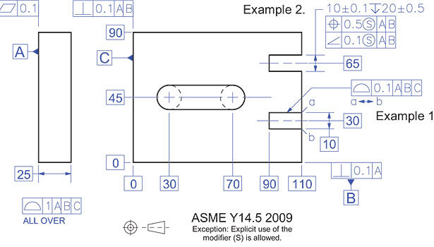
I was completely unsure why the 50mm basic is placed. That's easy if the slot has no draft. The true position is the exact coordinate, or location defined by basic dimensions or other means that represents the nominal value.
The length (horizontal dimension of the slot): It replaces the 1994 version. Composite tolerances are used when we have relatively looser location requirements but tighter orientation tolerances.
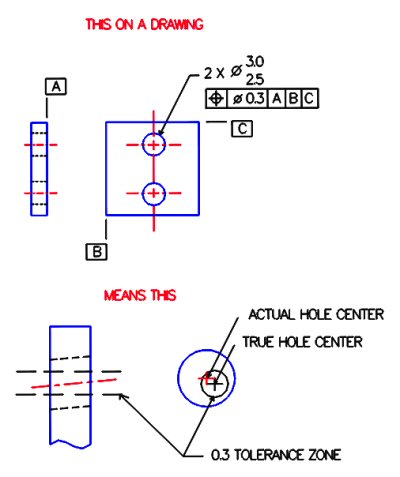
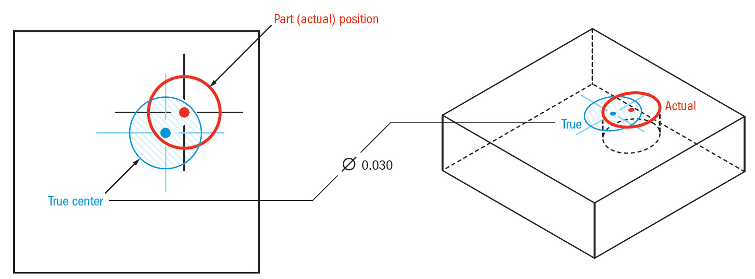
In other words, the gd&t position tolerance is how far your feature's location can vary from its true position. For example, when a hole’s true position is defined. Hole, slot) from its true position.
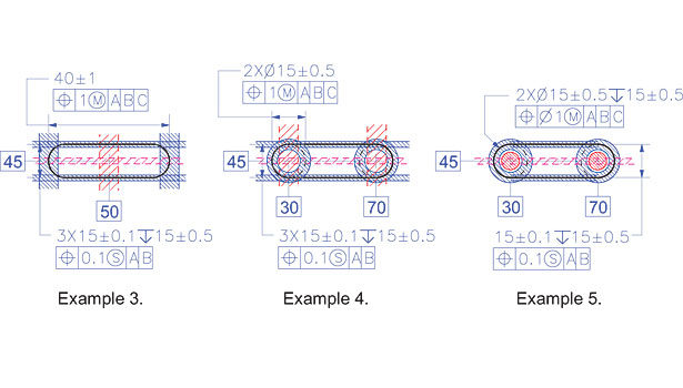
So we cannot define the entire slot as a feature of size. By the way, the location of the slot is not defined in the direction of the 50 basic, the position tolerance you show doesn't control that. Following the logic of using slots, this feature has the highest tolerances.
The true position is the exact coordinate, or location defined by basic dimensions or other means that represents the nominal value. Tolerance zone centered on true position of at least.020 in diameter. The true position tolerance in gd&t informs us of the maximum allowable deviation of a feature (e.g.
The idea is that, for a feature, there is a true position that we desire. In other words, the gd&t “position” tolerance is how far your feature’s location can vary from its “true position”. The following figures illustrate how tolerance of position controls the perpendicularity of a hole or a pin.
The basic dimensions are considered theoretically exact. The same principles apply if the tolerance of position is controlling a slot or a tab. But according to the iso rules for gd&t (gps), yes, position can be used on surfaces.
Diametrical actual tolerance = 2 x under root (0.15) square + (0.00) square. Recall that a tolerance of position must be applied to a feature of size. A simple example would be a set of holes (pattern) used to affix a name plate.
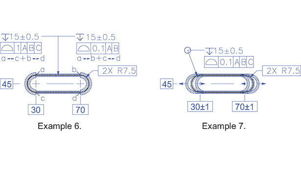
While maintaining the specified size limits of the elongated feature, no element of its surface shall be inside a theoretical boundary of identical. There is a position tolerance applied to the large hole on the left, and the datum being referenced is a. A position tolerance is the total permissible variation in the location of a feature about its exact true position.
Tolerance stacks gd&t store back to table of contents. The current standard for gd&t is asme y14.52009, from the american society of mechanical engineers. I am trying to grasp the concept of the round slot position callout.
In terms of the boundary for an elongated feature. But our slot has draft. Various modifiers such as mmc, lmc, projected tolerance can be used to define the true position of a feature.
Introduction to gd&t true position. A feature can be a hole, slot, or pin. The tolerance is only.010 in diameter, but it is specified with an mmc modifier;
Now let’s put all of that together by taking our first look at the gd&t concepts around. Gd&t provides a designer the tools to have clear, concise, and consistent instructions as to what is required. Consequently, bonus tolerance is available.
Position tol of a slot. You know how datums and feature control blocks work, for example. The figure below shows first a perpendicularity and then a tolerance of position.
The relative position of the holes is. We start with the goal of locating the the slot with a tolerance of position. Gd&t position tolerance controls the variation in the location of a feature from its true position.
Depending on how it is used, it may be The true position of the longitudinal center of the slot (center of the geometrical theoretical geometry). So the answer depends on which system is being imposed on the drawing!.
The position tolerance is the gd&t symbol and tolerance of location. We’ve picked up a lot of fundamentals in prior chapters. The rectangular box that contains a gd&t callout is known as the feature control frame. a geometric tolerance shown in a feature control frame is always total, not plus/minus.
It sounds a bit like using the flats on a horizontal slot to control the. Positional tolerances for cylindrical features, the position tolerance zone is typically a cylinder within which the axis of the feature must lie. The following formulas are used to calculate the bonus tolerance and total positional tolerance:
By true position, we mean the ideal position of the feature according to design.
Gdt In Precision Engineering Using Slots In Precision Location Article Faro
Gdt Best Practices 2013-04-01 Quality Magazine
Gdt Position Definition Emachineshop

How To Apply Gdt To A Slot - Youtube
Geometric Dimensioning Tolerancing Presentation Olcay Enel Olcay Enel

Mechanical Engineering Drawing Checking Review Services Mechanical Engineering Engineering Mechanic

Maximum Material Size Mmc Vs Feature Size Tolerance Chart Tool Calculator Tolerance Chart Tool Geometric
True Position Gdt Basics
Position Tolerance On Distance Basic Dimension - Drafting Standards Gdt Tolerance Analysis - Eng-tips
Gdt Position
Position Control Tolerance Geometric Dimension And Control
Gdt Best Practices 2013-04-01 Quality Magazine
Gdt Tip From Tec-ease - Tolerance Those Slots Right - Youtube
True Position Gdt Basics
Position Control Tolerance Geometric Dimension And Control

True Position Gdt Tolerance Calculator Gd And T Position Calculator Engineers Edge Positivity Tolerance True
Position Tolerance And Basic Dimensions Gdt Basics

True Position Gdt Basics
Gdt Best Practices 2013-04-01 Quality Magazine


0 Komentar